Fragments entering the meter can result in high, low or non-existent readings. This problem can be solved by using a filter or filter in front of the meter. These are recommended for instrument installations where debris or particles may be present in all flow meters . Check for debris to prevent the turbine from turning or picking up. Check the turbine for debris. Remove the internal device of the instrument for thorough observation, as some pieces, such as Teflon tape, cannot be seen by simply observing the instrument. Inspect rotor or shaft damage, bearing wear, external factors that actually reduce flow, such as valves, pressurization due to blockage, incorrect divisor, accumulator failure, or shaft break on one side of the rotor. (1) No reading at all (turbine does not rotate) (2) Low reading (fragment binding turbine) (3) High readings (shards spray fluid through the turbine) This ratio seems to be increasing, but the pressure has not changed. Check for accumulations in the meter and upstream piping, such as scale, paraffin, etc. (1) Part of the blockage of the instrument blockage (2) Partially closed valves or other restrictions upstream of the meter (3) Elbows, tees or other flow diverters are too close to the upstream end of the flowmeter viscosity of the fluid being measured (4) The flow meter or gasket in the flow tube is misaligned (5) Wax or scale accumulation in pipes or meters (6) Incorrect divisor (7) Accumulator failure. (8) The magnetic pickup has failed/faulted. (9) Noise from vibration or nearby energy sources. Check for debris at the upstream end of the turbine or changes in fluid conditions that may cause the gas to burst. Gas or air in the fluid can also cause high readings. A valve for rate control must be installed on the downstream side of the meter. Measure the reflux and add it to the regular flow, causing the accumulator to produce an excessively high value. Therefore, a leaky check valve can result in a high accumulator reading. Debris in the meter, broken shafts, viscous fluids, gas in the streamline or incorrect size or installation may result in inaccurate readings. Bearing wear on the shaft will appear as a dimple at the end of the shaft or a groove cut around the end of the shaft. When the groove is observed, the kit should be replaced. As a rule of thumb, if the dimple covers 66% of the surface area of ​​the shaft end, the kit should be replaced. If the groove on the shaft side can be felt, it should be replaced. Three Dimensional Composite Drainage Net,3d Composite Drainage Networks Geonet,3d Compound Geonet For Drainage,3D Composite Drainage Geonet Hebei Yintop Technology Co.ltd , https://www.yintopplasticfilm.com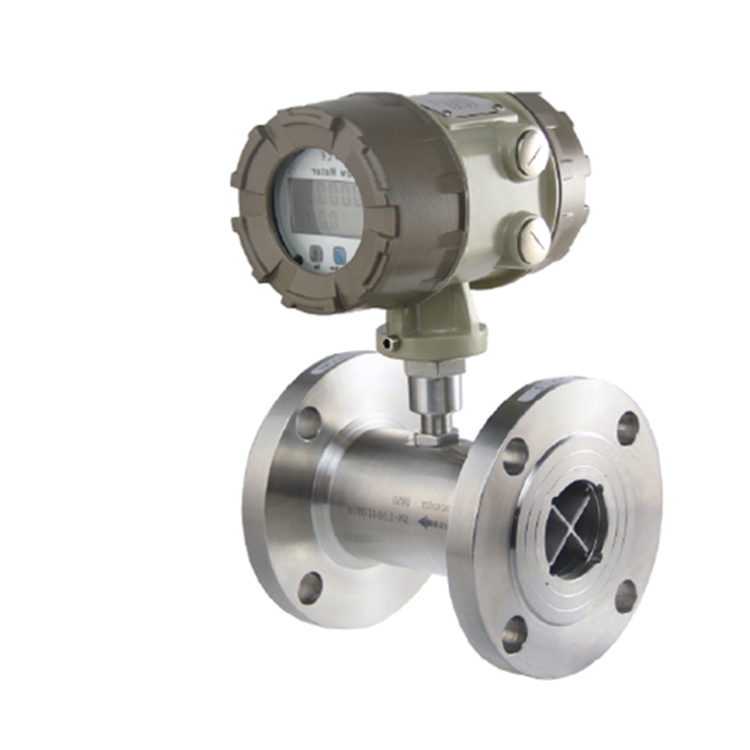 1. What is the most common problem with the meter?
Turbine flowmeter failure can be solved from the following eight aspects.